Waste Water Heat Recovery Equipments


I Natural Circulation type I Enforced Circulation type I Expected effects I Supermizer I


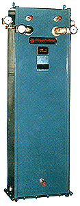
Supermizer, a high performance heat exchanger, has been developed with a view to export to the Japanese markets at the request of many public bathhouses of Japan, where the installation spaces for the bathhouses are relatively narrow and small.

<Characteristics>
*. Able to install in the small narrow areas from its compact design. *. Able to install on the aboveground or on the rooftop from its pumping method design.
*. Operating automatically only when wastewaters are fed into pumps.
*. Securing complete heat insulation that prevents freezing during the wintertime even when installed outside of the door.
*. Long equipment life using the durable cupronickel tubes.
*. High efficiency with use of specially designed spiral tubes.
<Operation methods>
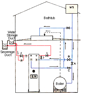
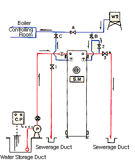
Close valve A at all times, while remaining opened valve B and valve C.
Normal mode operation with valve 1 and valve 2 closed, and valve 3 opened.
Start operation after opening all the air valves. Check the water flow into the air valve, and then close.
<Cleaning>
When daily operations are completed, switch off the pumps.
Close valve 3 and open valve 1 and valve 2, then reverse clean for a 1 ~ 2 minutes. Return to the original value conditions.


±â±â»ç¾ç


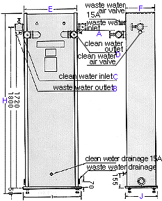
Standard Capacity

A

B

C

D

E

F

G

H

I

J

K

SM500-

10§©/H

50A

50A

50A

50A

590

320

500

2000

650

360

790

SM250-

5§©/H

50A

50A

50A

50A

490

250

430

2000

650

310

690


By flowing both hot water and cold water through the equipment under actual conditions, every heat exchanger manufactured in our plant is 100% thoroughly inspected before being shipped out. The equipments that passed the inspections are only put to the market.

¡åMeasurement Device for Surplus Recovery Performance


*. For measurement purposes only, the above specifications may change to some extent.


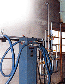
Installation and Tubing


<Operation>

<Cleaning>

¨ç Close valve A and open valve B and C at all times.
¨è Normal mode operation with valve 1 and valve 2 closed, and valve 3 opened.
¨é Start operation after opening all the air valves. Check the water flow into the air valve, and then close.

¨ç When daily operations are completed, switch off the pumps.
¨è Close valve 3, and open valve 1 and valve 2, then reverse clean for a 1 ~ 2 minutes, then return to the original value conditions.


 (\291.45/KWH)


Daily electric power rate

Monthly electric power rate

Operating hours

Electric power rate (\)

27days/month (\)

1 hour

117

3,159

2 hour

233

6,295

4 hour

466

12,591

8 hour

933

25,181

10 hour

1,166

31,477

12 hour

1,399

37,772


¡ØRequired pump capacity...1/2horsepower(0.4KWH)
¡Ø Power electric rate, with basis on the 2nd rate for business uses.


Underground Installation Diagram

Aboveground (Rooftop) Installation Diagram


------------------------------------------------------------------------------------------


Copyright¨Ï 2000 by HITEC ENERGY IND CO.,LTD. All rights reserved.
Sinsan-1ri 113-5 Gwangtan-myeon Paju-si Gyeonggi-do S.KOREA / Tel:82-31-947-1282